
Privacy statement: Your privacy is very important to Us. Our company promises not to disclose your personal information to any external company with out your explicit permission.
The suspension system is an important part of modern cars, which has a great influence on the ride comfort and steering stability of the car. The control arm (also called the swing arm) is used as the guiding and transmitting component of the car suspension system, and transmits various forces acting on the wheel to the vehicle body, while ensuring that the wheel moves according to a certain trajectory. The vehicle control arm elastically connects the wheel and the body through ball joints or bushings, respectively. The vehicle control arm (including the bushing and ball joint attached to it) should have sufficient rigidity, strength and service life. This article describes the structure and features of commonly used automotive control arms.
Automobile control arm ball joint assembly structure
First introduce the two common structural forms of the car control arm ball joint assembly. As shown in Figure 1, Figure 2.
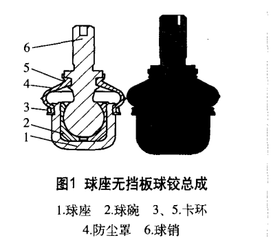
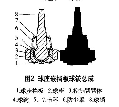
Car control arm structure
1. Lateral stabilizer bar connecting rod
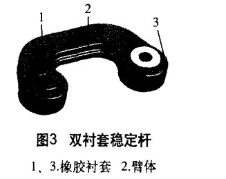
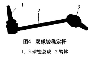
When the suspension is installed, one end of the stabilizer bar link is connected with the lateral stabilizer bar through the rubber bushing, and the other end is connected with the control arm or the barrel shock absorber through the rubber bushing or the ball joint, and the lateral stabilizer bar link is symmetric in the home selection. Used, it enhances the stability of operation.
The mechanism diagram of the two stabilizer bars is shown in Figure 3 and Figure 4. Figure 3 shows the double bushing stabilizer bar linkage. Figure 4 is a double ball hinge link.
2, tie rod
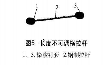
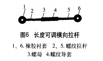
When the suspension is installed, the rubber bushing at one end of the tie rod is connected to the frame or the body, and the rubber bushing at the other end is connected to the hub. These control arms are mostly used in the multi-link suspension of the car and the tie rods of the steering system, which are mainly subjected to lateral loads and at the same time guide the movement of the wheels.
The structure of the two horizontal tie rods is shown in the figure below. Figure 5 is a non-adjustable lateral tie rod, and Figure 6 is an adjustable lateral pull rod.
3, the longitudinal tie rod
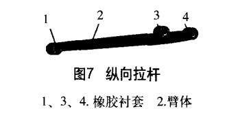
Longitudinal pull rods are mostly used for towing suspensions to transmit traction and braking force. Figure 7 is a structural view of a longitudinal tie rod. The arm body 2 is formed by press forming. The outer tubes of the rubber bushings 1, 3, 4 are welded to the arm body 2. The rubber bushing 1 is mounted on the force receiving portion in the middle of the vehicle body, the rubber bushing 4 is linked with the wheel hub, and the rubber bushing 3 is mounted on the lower end of the shock absorber to support and absorb shock.
4, single control arm
These automotive control arms are mostly used in multi-link suspensions, and the two single control arms work together to transmit lateral and longitudinal loads from the wheels.
Figure 8 is a structural view of a structural type overhanging control arm. The arm body 2 is a forged aluminum piece. The rubber bushing 1 is tightly fitted with the arm body 2, so that there is no relative movement between the rubber bushing 1 and the arm body 2. The ball joint assembly 3 is a ball seat embedded aluminum plate type, and the ball seat and the arm body 2 are assembled in an embedded manner.
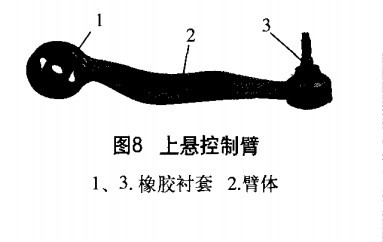
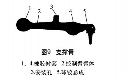
Figure 9 is another form of automotive control arm, also referred to as a support arm.
5, fork (V) arm
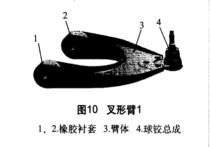
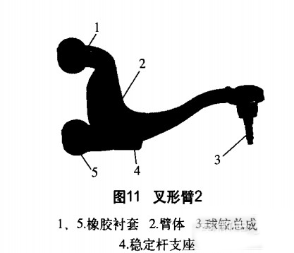
10 and 11 are structural views of two V-shaped arms. This type of vehicle control arm is mostly used for the lower arm of the upper and lower arms of the double wishbone independent suspension, and the fork-shaped structure of the arm mainly transmits the lateral load.
Structure and characteristics of the car control arm (2)
Time: 2011-08-24 17:20 Author: Cyberon Edit Source: Race Microelectronics Network
6, triangle arm
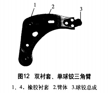
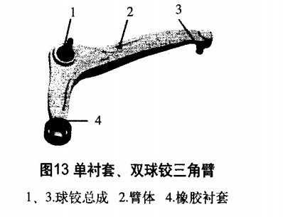
This type of vehicle control arm is mostly used for the lower arm of the front suspension McPherson suspension to transmit lateral and longitudinal loads and control the relative motion of the wheel and the body.
12 and 13 are structural views of two types of triangular arms. Figure 12 is a double bushing, single ball hinged triangular arm, and Figure 13 is a single bushing, double ball hinged triangular arm.
Enviar e-mail para este fornecedor

Privacy statement: Your privacy is very important to Us. Our company promises not to disclose your personal information to any external company with out your explicit permission.

Fill in more information so that we can get in touch with you faster
Privacy statement: Your privacy is very important to Us. Our company promises not to disclose your personal information to any external company with out your explicit permission.